
Module 9 – Guided Lab: Creating a Highly Available Environment
Module 9 – Guided Lab: Creating a Highly Available Environment
Lab overview and objectives
Critical business systems should be deployed as highly available applications—that is, applications remain operational even when some components fail. To achieve high availability in Amazon Web Services (AWS), we recommended that you run services across multiple Availability Zones.
Many AWS services are inherently highly available, such as load balancers. Many AWS services can also be configured for high availability, such as deploying Amazon Elastic Compute Cloud (Amazon EC2) instances in multiple Availability Zones.
In this lab, you will start with an application that runs on a single EC2 instance. You will then make the application highly available.
After completing this lab, you should be able to:
- Inspect a provided virtual private cloud (VPC)
- Create an Application Load Balancer
- Create an Auto Scaling Group
- Test the application for high availability
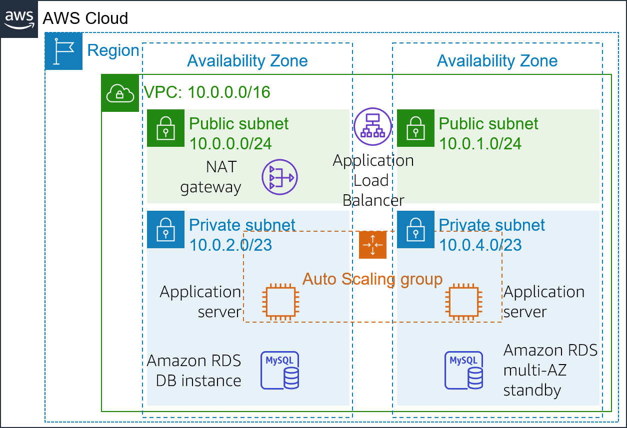
At the end of this lab, your architecture will look like the following example:

Duration
The lab requires approximately 40 minutes to complete.
AWS service restrictions
In this lab environment, access to AWS services and service actions might be restricted to the ones that are needed to complete the lab instructions. You might encounter errors if you attempt to access other services or perform actions beyond the ones that are described in this lab.
Accessing the AWS Management Console
- At the top of these instructions, choose Start Lab to launch your lab.
A Start Lab panel opens, and it displays the lab status.
Tip: If you need more time to complete the lab, restart the timer for the environment by choosing the Start Lab button again. - Wait until the Start Lab panel displays the message Lab status: ready, then close the panel by choosing the X.
- At the top of these instructions, choose AWS.
This action opens the AWS Management Console in a new browser tab. The system automatically logs you in.
Tip: If a new browser tab does not open, a banner or icon is usually at the top of your browser with the message that your browser is preventing the site from opening pop-up windows. Choose the banner or icon, and then choose Allow pop-ups. - Arrange the AWS Management Console tab so that it displays alongside these instructions. Ideally, you will have both browser tabs open at the same time so that you can follow the lab steps more easily.
Do not change the Region unless specifically instructed to do so.
Task 1: Inspecting your VPC
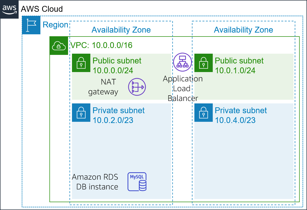
This lab begins with an environment that is already deployed via AWS CloudFormation. It includes:
- A VPC
- Public and private subnets in two Availability Zones
- An internet gateway (not shown) that is associated with the public subnets
- A Network Address Translation (NAT) gateway in one of the public subnets
- An Amazon Relational Database Service (Amazon RDS) instance in one of the private subnets

In this task, you will review the configuration of the VPC that was created for this lab.
- On the AWS Management Console, on the Services menu, choose VPC.
- In the left navigation pane, under Filter by VPC, click in the Select a VPC box and select Lab VPC.
This setting will limit the console to only show resources that are associated with the Lab VPC. - In the left navigation pane, choose Your VPCs.
Here, you can access information about the Lab VPC that was created for you.
The CIDR column has a value of 10.0.0.0/16, which means that this VPC includes all IP addresses that start with 10.0.x.x. - In the left navigation pane, choose Subnets.
Here, you can access information about Public Subnet 1:- The VPC column shows that this subnet exists inside of Lab VPC.
- The IPv4 CIDR column has a value of 10.0.0.0/24, which means that this subnet includes the 256 IP addresses between 10.0.0.0 and 10.0.0.255. Five of these addresses are reserved and unusable.
- The Availability Zone column lists the Availability Zone where this subnet resides.
- To reveal more details at the bottom of the page, select Public Subnet 1.
Tip: To adjust the size of the lower window pane, you can drag the divider. - In the lower half of the page, choose the Route Table tab.
This tab includes details about the routing for this subnet:- The first entry specifies that traffic destined within the Classless Inter-Domain Routing (CIDR) range for the VPC (10.0.0.0/16) will be routed within the VPC (local).
- The second entry specifies that any traffic destined for the internet (0.0.0.0/0) is routed to the internet gateway (igw-). This setting makes the subnet a public subnet.
- Choose the Network ACL tab.
This tab has information about the network access control list (network ACL) that is associated with the subnet. The rules currently permit all traffic to flow in and out of the subnet, but the rules can be further restricted by using security groups. - In the left navigation pane, choose Internet Gateways.
Notice that an internet gateway is already associated with Lab VPC. - In the left navigation pane, choose Security Groups.
- Select Inventory DB.
This security group controls incoming traffic to the database. - In the lower half of the page, choose the Inbound Rules tab.
These rules permit inbound MySQL or Aurora traffic (port 3306) from anywhere in the VPC (10.0.0.0/16). You will later modify this setting so it only accepts traffic from the application servers. - Choose the Outbound Rules tab.
By default, security groups allow all outbound traffic. However, this setting can be modified as needed.
Task 2: Creating an Application Load Balancer
To build a highly available application, it is a best practice to launch resources in multiple Availability Zones. Availability Zones are physically separate data centers (or groups of data centers) in the same Region. If you run your applications across multiple Availability Zones, you can provide greater availability if a data center experiences a failure.
Because the application runs on multiple application servers, you will need a way to distribute traffic amongst those servers. You can accomplish this goal by using a load balancer. This load balancer will also perform health checks on instances and only send requests to healthy instances.
- On the Services menu, choose EC2.
- In the left navigation pane, choose Load Balancers (you might need to scroll down to find it).
- Choose Create Load Balancer
Several types of load balancers are displayed. Read the descriptions of each type to understand their capabilities. - Under Application Load Balancer, choose Create
- For Name, enter: Inventory-LB
- Scroll down to the Availability Zones section, then for VPC, select Lab VPC.
You will now specify which subnets the load balancer should use. It will be a public load balancer, so you will select both public subnets. - Choose the first Availability Zone, then choose the Public Subnet that displays.
- Choose the second Availability Zone, then choose the Public Subnet that displays.
You should now have selected two subnets: Public Subnet 1 and Public Subnet 2. (If not, go back and try the configuration again.) - Choose Next: Configure Security Settings
A warning displays, which recommends that you use Secure HTTP (HTTPS) for improved security. This is good advice, but it is not necessary for this lab. - Choose Next: Configure Security Groups
You will now create a security group that accepts all incoming HTTP and HTTPS traffic. - Select Create a new security group, then configure:
- Security group name: Inventory-LB
- Description: Enable web access to load balancer
- Configure the existing rule (which is already on the page) as:
- Type: HTTP
- Source: Anywhere
- Choose Add Rule and configure:
- Type: HTTPS
- Source: Anywhere
- These settings will accept all incoming HTTP and HTTPS requests.
- Choose Next: Configure Routing
Target groups define where to send traffic that enters the load balancer. The Application Load Balancer can send traffic to multiple target groups based on the URL of the incoming request. An example could be sending requests from mobile apps to a different set of servers than other kinds of requests. Your web application will use only one target group. - For Name, enter: Inventory-App
- Expand Advanced health check settings.
The Application Load Balancer automatically performs health checks on all instances to ensure that they respond to requests. The default settings are recommended, but you will make them slightly faster for use in this lab. - Configure these values:
- Healthy threshold: 2
- Interval: 10
- These settings mean that the health check will be performed every 10 seconds. If the instance responds correctly twice in a row, it will be considered healthy.
- Choose Next: Register Targets
Targets are the individual instances that respond to requests from the load balancer. You do not have any web application instances yet, so you can skip this step. - Choose Next: Review
- Review the settings, choose Create and then choose Close
Your load balancer will now be provisioned in the background. You do not need to wait.
Task 3: Creating an Auto Scaling group
Amazon EC2 Auto Scaling is a service designed to launch or terminate Amazon EC2 instances automatically based on user-defined policies, schedules, and health checks. It also automatically distributes instances across multiple Availability Zones to make applications highly available.
In this task, you will create an Auto Scaling group that deploys EC2 instances across your private subnets, which is a security best practice for application deployment. Instances in a private subnet cannot be accessed from the internet. Instead, users send requests to the load balancer, which forward the requests to EC2 instances in the private subnets.

Create an AMI for Auto Scaling
You will create an AMI from the existing Web Server 1. This will save the contents of the boot disk so that new instances can be launched with identical content.
- In the AWS Management Console, on the Services menu, click EC2.
- In the left navigation pane, click Instances.
First, you will confirm that the instance is running. - Wait until the Status Checks for Web Server 1 displays 2/2 checks passed. Click refresh to update.
You will now create an AMI based upon this instance. - Select Web Server 1.
- In the Actions menu, click Image > Create Image, then configure:
- Image name: Web Server AMI
- Image description: Lab AMI for Web Server
- Click Create image
The confirmation screen displays the AMI ID for your new AMI. - Click Close
You will use this AMI when launching the Auto Scaling group later in the lab.
Create a Launch Configuration and an Auto Scaling Group
You will first create a launch configuration, which defines the type of instances that Amazon EC2 Auto Scaling should launch. The interface looks similar to when you launch an EC2 instance. However, instead of launching an instance, it stores the configuration for later use.
- In the left navigation pane, choose Launch Configurations.
- Choose Create launch configuration
- Configure these settings:
- Launch configuration name: Inventory-LC
- Amazon machine image (AMI) Choose Web Server AMI
- Instance type:
- Choose Choose instance type
- Select t3.micro
- Choose Choose
- Note: If you have launched the lab in the us-east-1 Region, select the t2.micro instance type. To find the Region, look in the upper right-hand corner of the Amazon EC2 console.
Note: If you receive the error message “Something went wrong. Please refresh and try again.”, you may ignore it and continue with the exercise. - Additional configuration
- IAM instance profile: Select Inventory-App-Role
- Monitoring: Select Enable EC2 instance detailed monitoring within CloudWatch
This allows Auto Scaling to react quickly to changing utilization.
- Expand Advanced details. Under User data, copy and paste this script:
#!/bin/bash
# Install Apache Web Server and PHP
yum install -y httpd mysql
amazon-linux-extras install -y php7.2
# Download Lab files
wget https://aws-tc-largeobjects.s3-us-west-2.amazonaws.com/ILT-TF-200-ACACAD-20-EN/mod9-guided/scripts/inventory-app.zip
unzip inventory-app.zip -d /var/www/html/
# Download and install the AWS SDK for PHP
wget https://github.com/aws/aws-sdk-php/releases/download/3.62.3/aws.zip
unzip aws -d /var/www/html
# Turn on web server
chkconfig httpd on
service httpd start
- Under Security groups
- Select an existing security group: Inventory-App
- You will receive a warning that You will not able to connect to the instance. You can ignore this warning because you will not connect to the instance. All configuration is done via the user data script.
- Under Key pair (login):
- Select Proceed without a key pair
- Select I acknowledge that…
- Choose Create launch configuration
The launch configuration defined what to launch, but the Auto Scaling group defines where to launch the resources.
- In the Launch configurations table, select Inventory-LC.
- From the Actions button, choose Create Auto Scaling group
- Enter Auto Scaling group name:
- Name: Inventory-ASG (ASG stands for Auto Scaling group)
- Choose Next
- On the Network page configure
- VPC: Lab VPC
- Subnet: Select Private Subnet 1 and Private Subnet 2
- You can ignore the warning that says No public IP addresses will be assigned. The EC2 instances will be launched in a private subnet, so they do not require public IP addresses.
This will launch EC2 instances in private subnets across both Availability Zones. - Choose Next
- Under Load balancing:
- Select Enable load balancing
- Choose Application Load Balancer or Network Load Balancer
- Choose a target group for your load balancer: Inventory-App
- These settings tell the Auto Scaling group to register new EC2 instances as part of the Inventory-App target group that you created earlier. The load balancer will send traffic to instances that are in this target group.
- Under Health checks:
- Select ELB
- Health check grace period: 90
- Under Additional settings:
- select Enable group metrics collection within CloudWatch
- Choose Next
- Under Group size, configure:
- Desired capacity: 2
- Minimum capacity: 2
- Maximum capacity: 2
- Under Scaling policies, choose None.
For this lab, you will maintain two instances at all times to ensure high availability. If the application is expected to receive varying loads of traffic, you can also create scaling policies that define when to launch or terminate instances. However, you do not need to create scaling policies for the Inventory application in this lab. - Choose Next
- On the Add notifications page, choose Next. You do not need to configure any of these settings.
- On the Add tags page, choose Add tag
- Key: Name
- Value: Inventory-App
- Select Next
- These settings will tag the Auto Scaling group with a Name, which will also appear on the EC2 instances that are launched by the Auto Scaling group. You can use tags to identify which Amazon EC2 instances are associated with which application. You could also add tags such as Cost Center to assign application costs in the billing files.
- On the Review page:
- Choose Create Auto Scaling group
- The Inventory-ASG will appear in the console:
The review shows that:- The group currently has no instances, but the information icon indicates that instances are being launched. (Hover over the icon for more details.)
- The Desired quantity is 2 instances. Amazon EC2 Auto Scaling will attempt to launch two instances to reach the desired quantity
- The Min and Max are also set to 2 instances. Amazon EC2 Auto Scaling will try to always provide two instances, even if failure occurs.
- Your application will soon run across two Availability Zones. Amazon EC2 Auto Scaling will maintain that configuration even if an instance or Availability Zone fails.
After a minute, choose Refresh to update the display. It should show that 2 instances are running.

Task 4: Updating security groups
The application you deployed is a three-tier architecture. You will now configure the security groups to enforce these tiers:

Load balancer security group
You already configured the load balancer security group when you created the load balancer. It accepts all incoming HTTP and HTTPS traffic.
The load balancer has been configured to forward incoming requests to a Target Group. When Auto Scaling launches new instances, it will automatically add those instances to the Target Group.
Application security group
The application security group was provided as part of the lab setup. You will now configure it to only accept incoming traffic from the load balancer.
- In the left navigation pane, choose Security Groups.
- Select Inventory-App.
- In the lower half of the page, choose the Inbound rules tab.
The security group is currently empty. You will now add a rule to accept incoming HTTP traffic from the load balancer. You do not need to configure HTTPS traffic because the load balancer was configured to forward HTTPS requests via HTTP. This practice offloads security to the load balancer, reducing the amount of work that is required by the individual application servers.
- Choose Edit inbound rules.
- On the Edit inbound rules page, choose Add rule and configure these settings.:
- Type: HTTP
- Source:
- Click in the search box next to Custom
- Delete the current contents
- Enter sg
- From the list that appears, select Inventory-LB
- Description: Traffic from load balancer
- Choose Save rules
The application servers can now receive traffic from the load balancer. This includes health checks that the load balancer performs automatically.
Database security group
You will now configure the database security group to only accept incoming traffic from the application servers.
- Select Inventory-DB (and make sure that no other security groups are selected).
The existing rule permits traffic on port 3306 (used by MySQL) from any IP address within the VPC. This is a good rule, but security can be restricted further.
- In the Inbound rules tab, choose Edit inbound rules and configure these settings:
- Click in the search box next to Custom
- Delete the current contents
- Type sg
- Select Inventory-App from the list that appears
- Description: Traffic from application servers
- Choose Save rules
You have now configured three-tier security. Each element in the tier only accepts traffic from the tier above.
In addition, the use of private subnets means that you have two security barriers between the internet and your application resources. This architecture follows the best practice of applying multiple layers of security.
Task 5: Testing the application
Your application is now ready for testing.
In this task, you will confirm that your web application is running. You will also test that it is highly available.
- In the left navigation pane, choose Target Groups.
The Inventory-App group of instances will be displayed. - In the lower half of the page, choose the Targets tab.
This tab should show two registered targets. The Status column shows the results of the load balancer health check that is performed against the instances. - In the top-right area, occasionally choose Refresh until the Status for both instances appears as healthy.
If the status does not eventually change to healthy, ask your educator for help with diagnosing the configuration. Hover over the icon in the Status column to access more information about the status.
You will test the application by connecting to the load balancer, which will then send your request to one of the EC2 instances. You will first need to retrieve the Domain Name System (DNS) name of the load balancer. - In the left navigation pane, choose Load Balancers.
- In the Description tab in the lower half of the window, copy the DNS Name to your clipboard.
It should be similar to: inventory-LB-xxxx.elb.amazonaws.com - Open a new web browser tab, paste the DNS name from your clipboard and press ENTER.
The load balancer forwarded your request to one of the EC2 instances. The instance ID and Availability Zone are shown at the bottom of the webpage. - Reload the page in your web browser. You should notice that the instance ID and Availability Zone sometimes change between the two instances.
When this web application displays, the flow of information is:- You sent the request to the load balancer, which resides in the public subnets that are connected to the internet.
- The load balancer chose one of the EC2 instances that reside in the private subnets and forwarded the request to it.
- The EC2 instance then returned the webpage to the load balancer, which returned it to your web browser.

Task 6: Testing high availability
Your application was configured to be highly available. You can prove the application’s high availability by terminating one of the EC2 instances.
- Return to the Amazon EC2 console tab in your web browser (but do not close the web application tab—you will return to it soon).
- In the left navigation pane, choose Instances.
You will now terminate one of the web application instances to simulate a failure. - Select one of the Inventory-App instances (it does not matter which one you select).
- Choose Actions then Instance State > Terminate.
- Choose Yes, Terminate
In a short time, the load balancer health checks will notice that the instance is not responding. The load balancer will automatically route all requests to the remaining instance. - Return to the web application tab in your web browser and reload the page several times.
You should notice that the Availability Zone that is shown at the bottom of the page stays the same. Though an instance failed, your application remains available.
After a few minutes, Amazon EC2 Auto Scaling will also notice the instance failure. It was configured to keep two instances running, so Amazon EC2 Auto Scaling will automatically launch a replacement instance. - Return to the Amazon EC2 console tab in your web browser. In the top-right area, choose refresh every 30 seconds until a new EC2 instance appears.
After a few minutes, the health check for the new instance should become healthy. The load balancer will continue to send traffic between two Availability Zones. You can reload your web application tab to see this happen.
This task demonstrates that your application is now highly available.
Optional task 1: Making the database highly available
This task is optional. You can work on this task if you have remaining lab time.
The application architecture is now highly available. However, the Amazon RDS database operates from only one database instance.
In this optional task, you will make the database highly available by configuring it to run across multiple Availability Zones (that is, in a Multi-AZ deployment).
- On the Services menu, choose RDS.
- In the left navigation pane, choose Databases.
- Choose inventory-db
Feel free to explore the information about the database. - Choose Modify
- For Multi-AZ deployment, select Yes.
You only need to do this one step to convert the database to run across multiple data centers (Availability Zones).
This option does not mean that the database is distributed across multiple instances. Instead, one instance is the primary instance, which handles all requests. Another instance will be launched as the standby instance, which takes over if the primary instance fails. Your application continues to use the same DNS name for the database. However, the connections will automatically redirect to the currently active database server.
You can scale an EC2 instance by changing attributes, and you can also scale an RDS database this way. You will now scale up the database. - For DB instance class, select db.t3.small.
This action doubles the size of the instance. - For Allocated storage, enter: 10
This action doubles the amount of space that is allocated to the database.
Feel free to explore the other options on the page, but do not change any values. - At the bottom of the page, choose Continue
Database performance will be impacted by these changes. Therefore, these changes can be scheduled during a defined maintenance window, or they can be run immediately. - Under Scheduling of Modifications, select Apply immediately.
- Choose Modify DB instance
The database enters a modifying state while it applies the changes. You do not need to wait for it to complete.
Optional task 2: Configuring a highly available NAT gateway
This task is optional. You can work on this task if you have remaining lab time.
The application servers run in a private subnet. If the servers must access the internet (for example, to download data), the requests must be redirected through a Network Address Translation (NAT) gateway. (The NAT gateway must be located in a public subnet).
The current architecture has only one NAT gateway in Public Subnet 1. Thus, if Availability Zone 1 fails, the application servers will not be able to communicate with the internet.
In this optional task, you will make the NAT gateway highly available by launching another NAT gateway in the other Availability Zone. The resulting architecture will be highly available:

- On the Services menu, choose VPC.
- In the left navigation pane, choose NAT Gateways.
The existing NAT gateway displays. You will now create a NAT gateway for the other Availability Zone. - Choose Create NAT gateway and configure these settings:
- Subnet: PublicSubnet2 (Select this option from the list)
Subnet details are at the beginning of these instructions. Choose Details, and to the right of AWS, choose Show. Note the names of PublicSubnet2 and NATGateway1. - Choose Allocate Elastic IP
- Choose Create NAT gateway
- Choose Edit route tables
- Subnet: PublicSubnet2 (Select this option from the list)
- You will now create a new route table for Private Subnet 2. This route table will redirect traffic to the new NAT gateway.
- Choose Create route table and configure these settings:
- Name tag: Private Route Table 2
- VPC: Lab VPC
- Choose Create and then choose Close
- Select Private Route Table 2, and confirm that it is the only route table that is selected.
- Choose the Routes tab.
Currently, one route directs all traffic locally.
You will now add a route to send internet-bound traffic through the new NAT gateway. - Choose Edit routes and then configure these settings:
- Choose Add route
- Destination: 0.0.0.0/0
- Target: Select NAT Gateway, then select the nat- entry that is not the entry for NATGateway1 (which is under the Details button above these instructions)
- Choose Save routes and then choose Close
- The NAT gateway that is listed under the Details button (which is above these instructions) is for Public Subnet 1. You are configuring the route table to use the other NAT gateway.
- Choose the Subnet Associations tab.
- Choose Edit subnet associations
- Select Private Subnet 2.
- Choose Save
This action now sends internet-bound traffic from Private Subnet 2 to the NAT gateway that is in the same Availability Zone.
Your NAT gateways are now highly available. A failure in one Availability Zone will not impact traffic in the other Availability Zone.
Submitting your work
- At the top of these instructions, choose Submit to record your progress and when prompted, choose Yes.
- If the results don’t display after a couple of minutes, return to the top of these instructions and choose Grades
Tip: You can submit your work multiple times. After you change your work, choose Submit again. Your last submission is what will be recorded for this lab. - To find detailed feedback on your work, choose Details followed by View Submission Report.
Lab complete
Congratulations! You have completed the lab.
- Choose End Lab at the top of this page, and then select Yes to confirm that you want to end the lab.
A panel indicates that DELETE has been initiated… You may close this message box now. - Select the X in the top right corner to close the panel.


